It’s been a while since I finished the CHIP-8 emulator, the CHIP-8 emulator was mostly capable of running PONG, but at the end I still haven’t figured out how to get input work correctly. This time I want to try to experiment with the Gameboy, it will be much harder to emulate given the increased number of instructions and a palette.
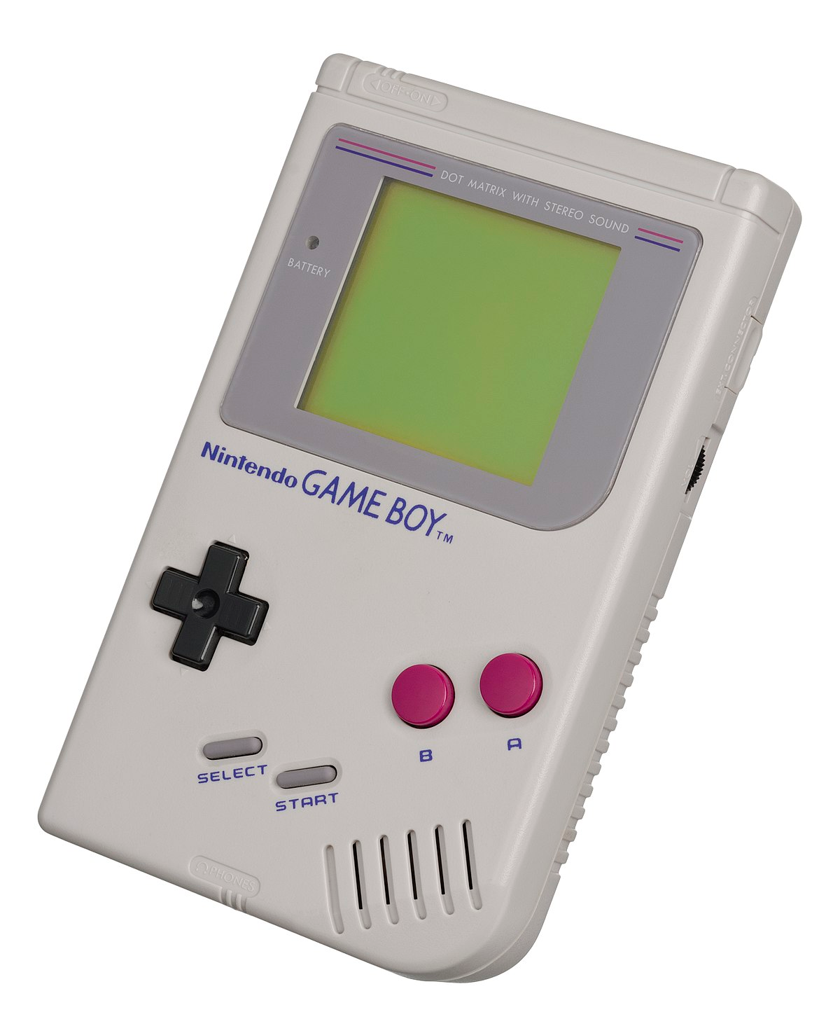
DMG-01

Also known as the “original gameboy”

Hardware Overview

  • CPU: Custom 8-bit sharp at 4.19MHZ
  • Resolution: 160*144
  • Framerate: 59.727hz
  • Memory: 8KiB internal S-RAM
  • VRAM: 8KiB
  • Color: 2-bit, 4 shades of “gray”
  • Input Dpad + action buttons
  • Serial I/O (Link Cable)

CPU

  • 7 8-bit register (A,B,C,D,E,H,L)
  • 5 16-bit register (HL, BC, DE, AF)
  • 1 Flag register (Z, H, N, C)
  • Stack pointer register (16-bit)
  • Program Counter register (16-bit)

Also includes:

  • Pixel Processing Unit (PPU)
  • Audio Processing Unit (APU)
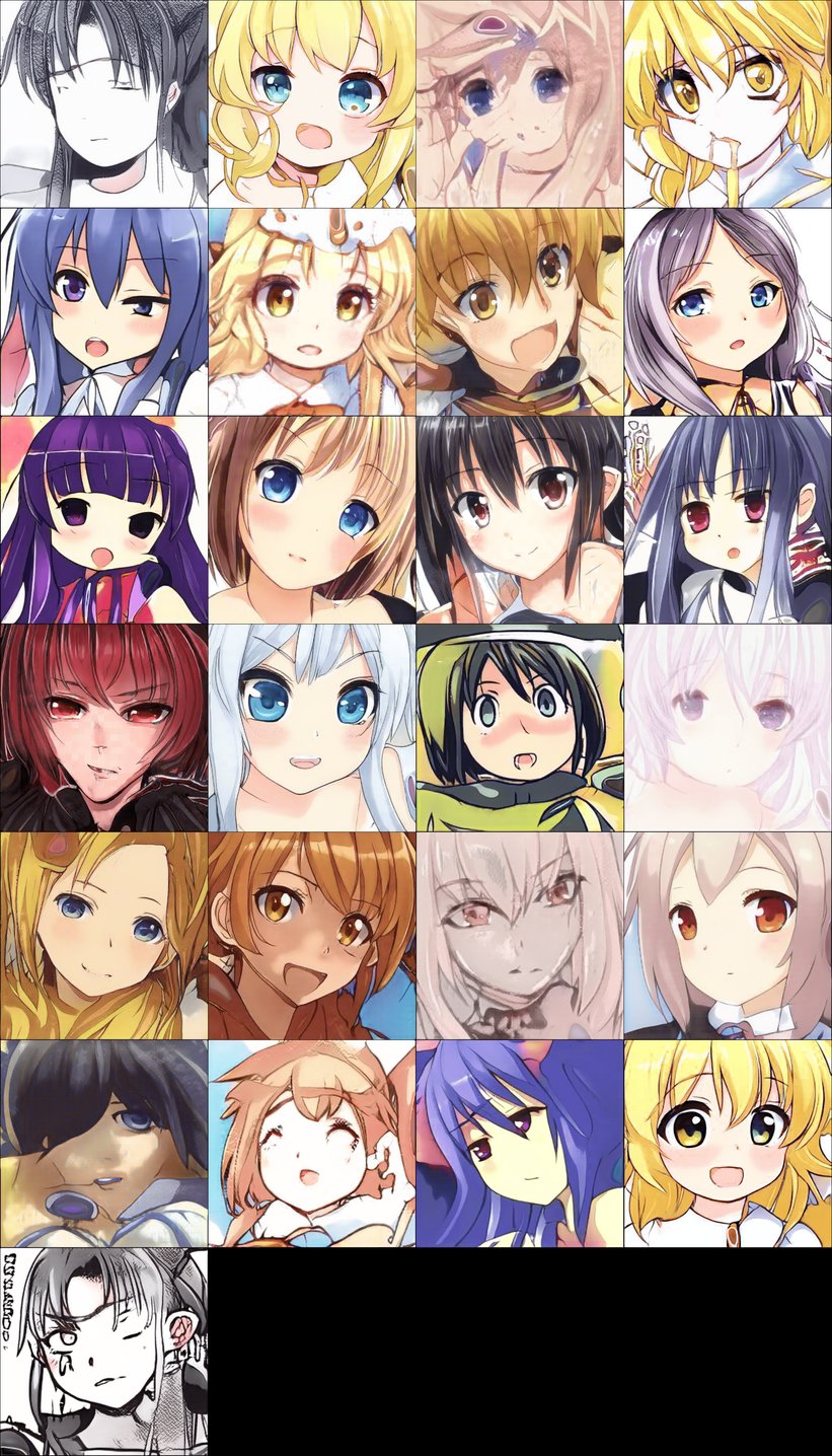
Graphics

  • OAM stores the sprite information, used during rendering
  • Palette stores color information, determine how a sprite appears on the screen
  • Tile data + tile maps is loaded from cartridge at startup to the VRAM

Anti Piracy

  • Done in bootrom
  • After the scrolling of the logo, bootrom will check the logo stored in the bootrom against the one in cartridge.
  • If checksum match, will disable bootrom and jump to the cartridge and start executing.
  • If checksum fails, the console will freeze (jump loop)

Due to the logo is copyrighted and trademarked by Nintendo, pirated and un-licensed games will not be including this logo in their cartridge unless they are ready to face Nintendo’s legal department.

Building the emulator

  • There is no magic. 💫
  • Each component is pretty straight forward to emulate if you have the spec sheet.
  • We can treat CPU just a block of code that modify internal state + memory when given input
  • We can treat the PPU as a block code that takes some internal state and render it to a picture.

Emulating CPU

1
2
3
4
5
6
pub struct Core {
pub memory: Rc<RefCell<dyn Memory>>,
pub registers: Registers,
pub halted: bool,
pub ei: bool,
}
  • Quite simple if you know the CPU specs already
  • Implement every register and instruction.
  • Implement a opcode decoder
  • Implement clock limiter to limit execution to exactly 4 mhz according to spec

Example: INC r/d8

Instruction Decode

1
2
3
4
5
6
7
instruction_set.insert(
0x04,
Instruction::new("inc b", 0x04, 0, Box::new(increment_b)),
);
fn increment_b(core: &mut Core, _: Option<Operand>) {
core.registers.b = core.alu_inc(core.registers.b);
}

Execution

1
2
3
4
5
6
7
8
// Increment number
pub fn alu_inc(&mut self, n: u8) -> u8 {
let result = n.wrapping_add(1);
self.registers.set_flag(Flag::H, (n & 0x0f) + 0x01 > 0x0f);
self.registers.set_flag(Flag::N, false);
self.registers.set_flag(Flag::Z, result == 0x00);
result
}
  • Instruction decoder will decode the 0x04 value from the rom as INC B (increment B register by 1)
  • Inside the CPU module, when this instruction is seen, execute the method alu_inc with the value of B.
  • Result is returned to the B register and CPU flags is adjusted according to spec

Emulating MBC

  • Gameboy has only 16-bit addressing
  • For larger games, ROM and RAM needs to be banked so a larger address space can be addressed.
  • Many types of MBC exist but common ones are MBC1, MBC3, MBC5
1
2
3
4
5
6
7
8
9
10
11
12
13
14
15
16
17
18
19
20
21
22
pub fn load_cartridge(rom: Vec<u8>) -> Box<dyn Cartridge> {
if rom.len() < 0x8000 || rom.len() % 0x4000 != 0 {
panic!("Invalid length: {} bytes", rom.len());
}

let ram_size_byte = rom[0x149];
let ram_size = CartridgeRamSize::from_u8(ram_size_byte)
.expect(format!("Incorrect RAM size {:04x}", ram_size_byte).as_str());
let cartridge: Box<dyn Cartridge> = match rom[0x147] {
0x00 => Box::new(Rom::new(rom)),
0x01 => Box::new(Mbc1::new(rom, ram_size as usize)),
0x13 => Box::new(Mbc3::new(rom, ram_size as usize)),
_ => unimplemented!(),
};

debug!("Loaded cartridge: {}", cartridge.title());
debug!("Cartridge type is: {}", cartridge.get_cart_info());
debug!("Cartridge rom size is: {:?}", cartridge.get_rom_size());
debug!("Cartridge ram size is: {:?}", cartridge.get_ram_size());

cartridge
}
  • Determine cartridge type at 0x147.
  • Return an MBC type according to the cartridge type.

Example MBC1 read

  • Each MBC has address space that is banked and unbanked
  • When accessing spaces that is banked, according the spec, we need to adjust the actual address we are reading from according to the current bank selection.
  • The implementation uses a Vector.
  • We will need to translate the memory address into an index for that Vector
1
2
3
4
5
6
7
8
9
10
11
12
13
14
15
16
17
18
19
20
21
22
23
24
25
26
27
28
fn get(&self, address: u16) -> u8 {
match address {
0x0000..=0x3fff => self.rom[address as usize],
0x4000..=0x7fff => {
let selected_bank = if self.bank_mode == BankMode::Ram {
self.bank & 0x1f
} else {
self.bank & 0x7f
} as usize;
let offset = selected_bank * 0x4000;
self.rom[address as usize - 0x4000 + offset]
}
0xa000..=0xbfff => {
if self.ram_enabled {
let selected_bank = if self.bank_mode == BankMode::Ram {
(self.bank & 0x60) >> 5
} else {
0x00
} as usize;
let offset = selected_bank * 0x2000;
self.ram[address as usize - 0xa000 + offset]
} else {
0x00
}
}
_ => 0x00,
}
}

Emulating MMU

1
2
3
4
5
6
7
8
9
10
11
12
13
14
pub struct MMU {
pub boot_rom: Option<[u8; 256]>,
pub cartridge: Box<dyn Cartridge>,
pub ppu: RefCell<PPU>,
pub joypad: JoyPad,
boot_rom_enabled: bool,
timer: Timer,
last_serial: u8,
work_ram: [u8; 0x8000],
high_ram: [u8; 0x7f],
work_ram_bank: usize,
interrupt_flags: Rc<RefCell<InterruptFlags>>,
interrupt_enabled: u8,
}
  • This is a easy part since MMU basically just something that exposes to the CPU and provide basic memory read and write
  • The MMU will send read/write command to other components (PPU, APU)
  • MMU will also maintain the work ram and timer.

Example of MMU read

1
2
3
4
5
6
7
8
9
10
11
12
13
14
15
16
17
18
19
20
21
22
23
24
25
26
27
28
29
30
31
32
33
34
35
36
37
38
39
40
41
42
43
fn get(&self, address: u16) -> u8 {
match address {
// Last instruction is at 0xfe and its two bytes, therefore excluding 0xff from rom addressing
0x0000...0x7fff => {
if self.boot_rom_enabled && self.boot_rom != None && address < 0x100 {
self.boot_rom.unwrap()[address as usize]
} else {
self.cartridge.get(address)
}
}
0x8000..=0x9fff => self.ppu.borrow().get(address),
0xa000..=0xbfff => self.cartridge.get(address),
0xc000..=0xcfff => self.work_ram[address as usize - 0xc000],
0xd000..=0xdfff => {
self.work_ram[address as usize - 0xd000 + 0x1000 * self.work_ram_bank]
}
0xe000..=0xefff => self.work_ram[address as usize - 0xe000],
0xf000..=0xfdff => {
self.work_ram[address as usize - 0xf000 + 0x1000 * self.work_ram_bank]
}
0xfe00..=0xfe9f => self.ppu.borrow().get(address),
0xfea0..=0xfeff => 0x00, // Invalid address
0xff00 => self.joypad.get(address),
0xff01..=0xff02 => {
// Serial
0
}
0xff04..=0xff07 => {
// Clock
self.timer.get(address)
}
0xff0f => self.interrupt_flags.borrow_mut().data,
0xff10..=0xff3f => {
// APU
0
}
0xf40...0xff4b => self.ppu.borrow().get(address),
0xff68..=0xff6b => self.ppu.borrow().get(address),
0xff80..=0xfffe => self.high_ram[address as usize - 0xff80],
0xffff => self.interrupt_enabled,
_ => 0x0000,
}
}
  • Basically it’s just a thing that send read/write operation to the proper devices.
  • The range of address for each device is the memory map for the gameboy.

Debugging without graphics

  • Looking at trace log of each instruction running on the CPU
  • Look at the register dump to see if the CPU did exactly what it should.
  • Efficient when you know which instruction caused the problem
  • Horrible for eyesight.
  • Copy your CPU code into someone else’s project and integrate it.

Blargg’s test

1
2
3
4
5
6
7
8
9
10
0xff01..=0xff02 => {
// Serial
if address == 0xff01 {
self.last_serial = value;
}
if address == 0xff02 {
print!("{}", self.last_serial as char);
input::stdout().flush();
}
}
  • Has most of the test roms needed to make sure your implementation is correct.
  • Does not require display to show result!
  • Test output result to serial, its easy to hook that up in MMU set and output the character written to serial

Emulating PPU

1
2
3
4
5
6
7
8
9
10
11
12
13
14
15
16
17
18
19
20
21
22
23
24
25
26
27
28
29
30
31
32
33
34
35
36
37
38
39
40
41
42
pub struct PPU {
pub interrupt_flags: Rc<RefCell<InterruptFlags>>,
pub framebuffer: PPUFramebuffer,
pub tile_set: [Tile; TILE_MAP_SIZE],
pub video_ram: [u8; VRAM_SIZE],
pub oam: [u8; OAM_SIZE],
pub mode: Mode,
sprites: [Sprite; 40],

bgp: u8, // Background sprite

// This register assigns gray shades for sprite palette 0. It works exactly as BGP (FF47), except that the lower
// two bits aren't used because sprite data 00 is transparent.
op0: u8,
// This register assigns gray shades for sprite palette 1. It works exactly as BGP (FF47), except that the lower
// two bits aren't used because sprite data 00 is transparent.
op1: u8,

// Window Y Position (R/W), Window X Position minus 7 (R/W)
wy: u8,
wx: u8,

mode_clock: u32,
ly: u8,
scroll_x: u8,
scroll_y: u8,
lcdc_display_enabled: bool,
lcdc_window_tilemap: bool,
lcdc_window_enabled: bool,
lcdc_bg_and_window_tile_base: bool,
lcdc_bg_tilemap_base: bool,
lcdc_obj_sprite_size: bool,
lcdc_obj_sprite_display_enabled: bool,
lcdc_bg_enabled: bool,
ly_coincidence: u8,
ly_coincidence_interrupt_enabled: bool,
mode_0_interrupt_enabled: bool,
mode_1_interrupt_enabled: bool,
mode_2_interrupt_enabled: bool,
horiz_blanking: bool,
tick_counter: u64,
}
  • PPU handles all the draw and refresh.
  • Has 4 mode, and control registers.
  • Has 4 palette that program can freely choose
  • Has OAM storage for storing sprite information
  • Internal framebuffer for rendering
  • Need to support DMA for oam loading
  • This video will explain it better than I will ever be https://youtu.be/HyzD8pNlpwI?t=1747

Example PPU draw

1
2
3
4
5
6
7
8
9
10
11
12
13
14
15
16
17
18
19
20
21
22
23
24
fn render_scanline(&mut self) {
trace!("Rendering scanline, {:?}", self.mode);
self.render_background();
self.render_sprites();
}

fn change_mode(&mut self, mode: Mode) {
self.mode = mode;
if match self.mode {
Mode::HBlank => {
self.render_scanline();
self.horiz_blanking = true;
self.mode_0_interrupt_enabled
}
Mode::VBlank => {
self.interrupt_flags.borrow_mut().hi(Flag::VBlank);
self.mode_1_interrupt_enabled
}
Mode::OAMRead => self.mode_2_interrupt_enabled,
Mode::VRAMRead => false,
} {
self.interrupt_flags.borrow_mut().hi(Flag::LCDStat);
}
}
  • During HBlank mode we draw the current scanline
  • During VBlank mode, the PPU is not using the VRAM anymore, and we can raise the VBlank interrupt to the CPU so it can be handled.
  • When we want the mode to trigger an interrupt, we will raise it here as well.
  • Interrupt is used often to notify something is being drawn on the LCD

Putting everything together

1
2
3
4
5
6
7
8
9
10
11
12
13
14
15
16
17
18
19
20
21
22
23
24
25
26
27
28
29
30
31
32
33
34
35
pub struct Emulator {
pub mmu: Rc<RefCell<MMU>>,
pub cpu: ClockedCPU,
}

impl Emulator {
pub fn new(boot_rom: Option<Vec<u8>>, rom: Vec<u8>) -> Emulator {
let has_bootrom = match boot_rom {
None => false,
_ => true,
};
let mmu = Rc::new(RefCell::new(MMU::new(boot_rom, rom)));
let mut cpu = ClockedCPU::new(mmu.clone());

// If no boot rom is set, we simulate the boot rom states on the mmu and cpu
if !has_bootrom {
mmu.borrow_mut().simulate_boot_rom();
cpu.simulate_boot_rom();
}

Self { cpu, mmu }
}

pub fn tick(&mut self) -> u32 {
// Execute one cpu cycle
let cycles = self.cpu.tick();
// Update the mmu with the cycles
self.mmu.borrow_mut().tick(cycles);
cycles
}

pub fn should_refresh_screen(&self) -> bool {
self.mmu.borrow().ppu.borrow().mode == Mode::VBlank
}
}
  • Reading the rom file and decode each instruction
  • Hooking up CPU and MMU, allow CPU to directly read write in MMU
  • Hooking up MMU and PPU, allow MMU to dispatch read/write to PPU
  • Updating MMU and PPU at each clock ticks so interrupts can be handled and data can be updated
  • Using a window library to draw the framebuffer from the PPU on screen at each screen refresh.

Final result

After 2 month of CPU rewriting, and dozen of bugs squashed, the emulator finally able to run games like Tetris or Pokemon Red

Running Tetris

  • Bootrom works and scrolling nintendo logo appeared.
  • Tiles in VRAM is also displayed on screen.
  • Useful debug information about the CPU registers is also displayed.

Running Pokemon Red

Know Issues

  • No APU (no sound)
  • Pokemon Red (MBC3) has some banking bug that crashes the emulator
  • No Input
  • No Serial
  • No MBC5 support
  • Sprite priority is weird, (sometimes works sometimes doesn’t)
  • Double sized sprite not yet supported.

The full project can be found here